Multilayer Adaptive Thin Shell Reflectors for Future Space Telescopes
- scmero
- Dec 3, 2020
- 2 min read
Updated: Dec 28, 2020
1. Demonstrators
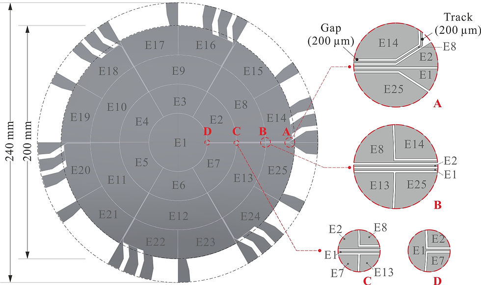
This project is intended to explore the technology of controlling the shape of a thin spherical reflector shell by means of a thin layer electrostrictive material (PVDF‐TrFE). It involves the manufacturing and testing of two demonstrators. The first one (realised during the first phase of the project) has a diameter of 100mm and a radius of curvature of 2.5m and is controlled by 7 independent electrodes. The second one (Phase 2) has a diameter of 200mm and is controlled by 25 independent electrodes. Figure 1 shows a view of the two demonstrators while Figure 2 shows the distribution of the electrodes of the second demonstrator; all electrical connections are on the edge of the reflector.

Figure 1: Demonstrators developed in the MATS project, mounted in their support.
Left: Phase 1, Spin coated. Right: Phase 2, Spray coated.

Figure 2: Keystone electrodes layout and electrical connections.
2. Material properties
Figure 3 shows the material distribution and the thickness of the various layers. The main material properties are reported in Table 1.

Figure 3: Material distribution and thickness of the various layers.
Table 1: Estimation on material parameters (PVDF-TrFE).

3. Metrology, Influence functions
The influence functions of the 25 control electrodes have been measured using a laser vibrometer; the various electrodes are excited harmonically in the quasi‐static range (well below the first resonance) and the amplitude of the reflector response is measured with the vibrometer. Figure 4 shows two typical influence functions corresponding to a voltage amplitude of 100V. The figure shows also a cross section in the reflector shape and a comparison with a finite element simulation.

Figure 4: Experimental influence functions of electrodes E1 and E2. Cross section at 45°
in the reflector shape and comparison with a finite element simulation.
The optical modes can be reconstructed by combining the various influence functions and inverting the equation

where z is the optical mode to reconstruct, J is the Jacobian matrix (the columns of J are the influence functions and x is the vector of voltages to apply to the electrodes. The ill‐conditioning of the Jacobian can be alleviated using the Damped Least Squares (DLS) which leads to the pseudo‐inverse:

The damping factor α2 handles the conflicting requirements of minimizing the fitting error and limitingthe control actuator voltage budget ΔV. Figure 5 illustrates the procedure for the trefoil mode with a PV amplitude of 5 μm in a pupil of 120 mm.

Figure 5: Trefoil mode with a PV amplitude of 5 μm in a pupil of 120 mm. (a) L‐curve showing the trade‐off between the voltage budget and the fitting error. (b) From left to right: Reflector shape in the pupil, fitting error and voltage map for α = 2×10‐7.
Relevent Papers
K. Wang, D. Alaluf, G. Rodrigues, A. Preumont, Precision Shape Control of Ultra-thin Shells with Strain Actuators. Journal of Applied and Computational Mechanics, 2020.
K. Wang, T. Godfroid, D. Robert, A. Preumont, Electrostrictive PVDF-TrFE Thin Film Actuators for the Control of Adaptive Thin Shell Reflectors. Actuators 9(3), 53, 2020.


Comments